
COILED TUBING UNIT
Coiled tubing (CT) is a generic name often used for coiled tubing services (CTS). Operationally, a CT intervention involves pushing a coiled tubing string into an oil or gas well to perform work without disturbing the existing well completion. The ability to pump through the CT string allows many different types of operations be carried out. At the end of a CT operation, the CT string is pulled out of the well and spooled back onto the CT reel CTUs are often described as the following:
- Power Pack
- Control Cabin
- Reel
- Injector Head
- Pressure Control Equipment
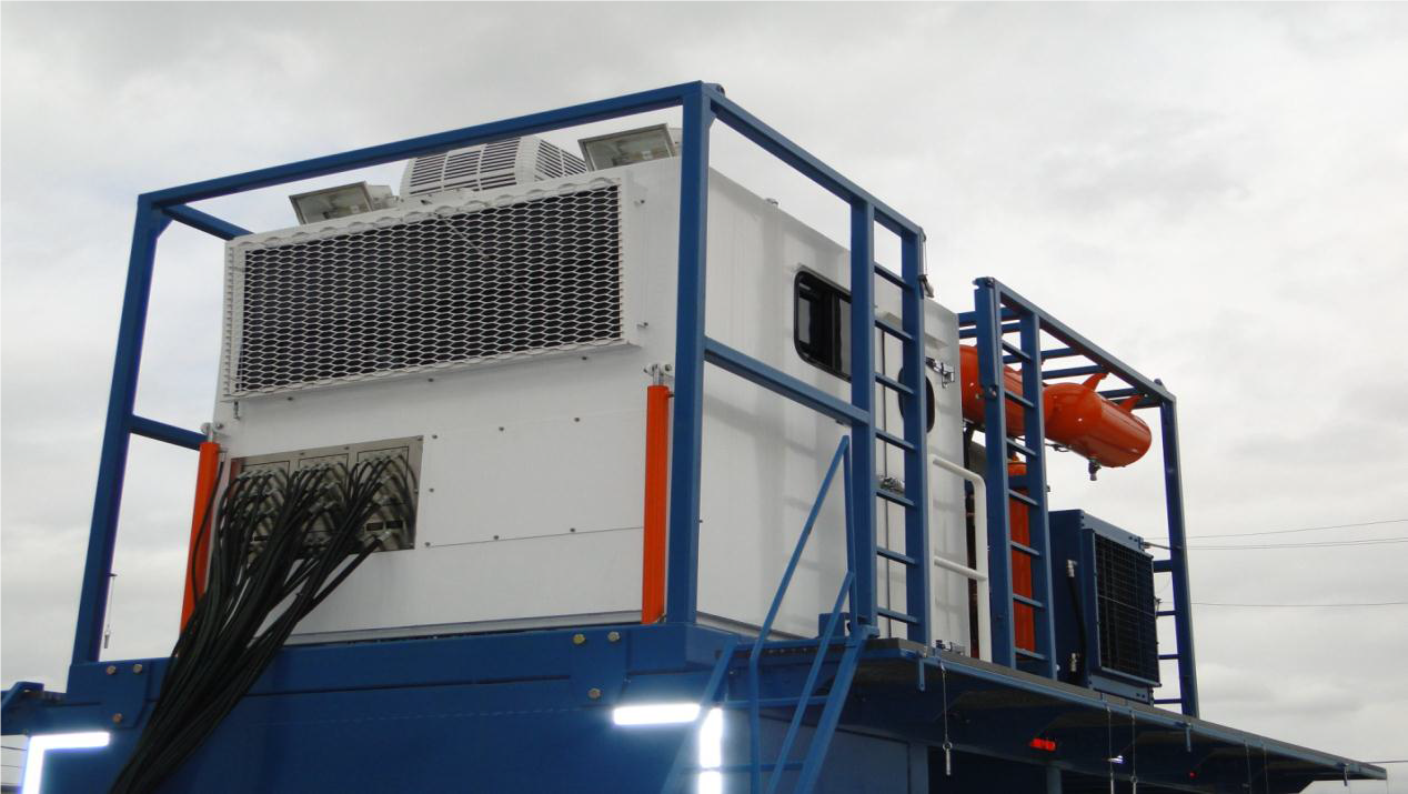
POWER PACK FUNCTION
The CTU power pack, also called the prime mover, is usually a diesel engine (see Fig.1). The power pack provides hydraulic power through a system of pumps, valves, and lines, to operate the CTU functions and controls. The system comprises multiple hydraulic circuits.

CONTROL CABIN FUNCTION
The CT operator controls the power pack hydraulic systems from the control console. The console includes all the controls and gauges required by the CT operator to control and monitor operation of all CTU components
REEL FUNCTION
The primary function of the reel assembly is to store and protect the CT string. The reel system uses the reel drum and crash frame to perform this function. The reel also performs several other functions
including the following:
- Maintains proper tension between the reel and the injector head
- Efficiently spools the CT string onto the reel Drum
- Circulates fluids through the CT string with the reel drum rotating
- Allows the introduction of balls or darts into the CT string.
Provides a mounting for the tubing Lubrication, monitoring, and measuring equipment
The reel equipment is grouped into the following systems or assemblies:
- Reel drum
- Reel Drive and Brake System
- Level Wind Assembly
- Depth Counter
- Lubrication System
- Reel Swivel and Manifold
Technical Specifications
Dimensions: Height 141 in.
Length 171.5 in.
Width 102 in.
Weights: Weight (empty) 16,190 lbs.
INJECTOR HEAD ASSEMBLY
The injector head (see Fig.3) pulls, pushes, holds, and guides the CT string. The equipment that performs these operations is grouped into the following systems:
- Drive and brake system
- Chain assembly
- Traction and tension system
- Guide arch system.
From the control console, the CT operator can remotely operate the components mounted on the injector head using specific hydraulic circuits. The hydraulic circuits allow the operator to exercise a high degree of control over any movement of the CT string.

Figure 3
| Description | Pull/Push | Pressure required |
| Rated Pull | 80,000 lbf. Pull | 3700 psig |
| Pull at min. Displacement | 40,000 lbf. Pull | 5000 psig |
| Snub load at full displacement | 40,000 lbf. Push | 1900 psig |
PRESSURE CONTROL EQUIPMENT
Generally, these barriers are classified according to the following three categories (see also Fig. 4):
- Primary barrier: The primary barrier is the one in use during normal operations. In CT
- operations, the stripper (including dual or tandem strippers) is the primary barrier.
- Secondary barrier: The secondary barrier is brought into operation if the primary barrier is
- compromised. It is not applied during normal operations. In CT operations, the secondary barrier is the blowout preventer (BOP).
- Tertiary Barrier: The tertiary barrier is operated on a contingency or emergency basis, being brought into operation as a last resort. The use of a tertiary barrier usually depends on several factors, including well bore conditions. Typically in CT operations, this barrier is a shear/seal BOP fitted directly on the wellhead.

Figure 4
TWIN PUMPING UNIT
The Twin-pump unit provides high-horsepower .
Pumping services up to 10,000 psig (see Fig. 5). The mixing and pumping functions are fully redundant.
Application
The Twin-pump is used for:
- Cementing services (primary and remedial cementing)
- Acidizing Services
- High-horsepower, high-pressure pumping Services
- Pressure testing services
- Pumping a variety of fluids from remote
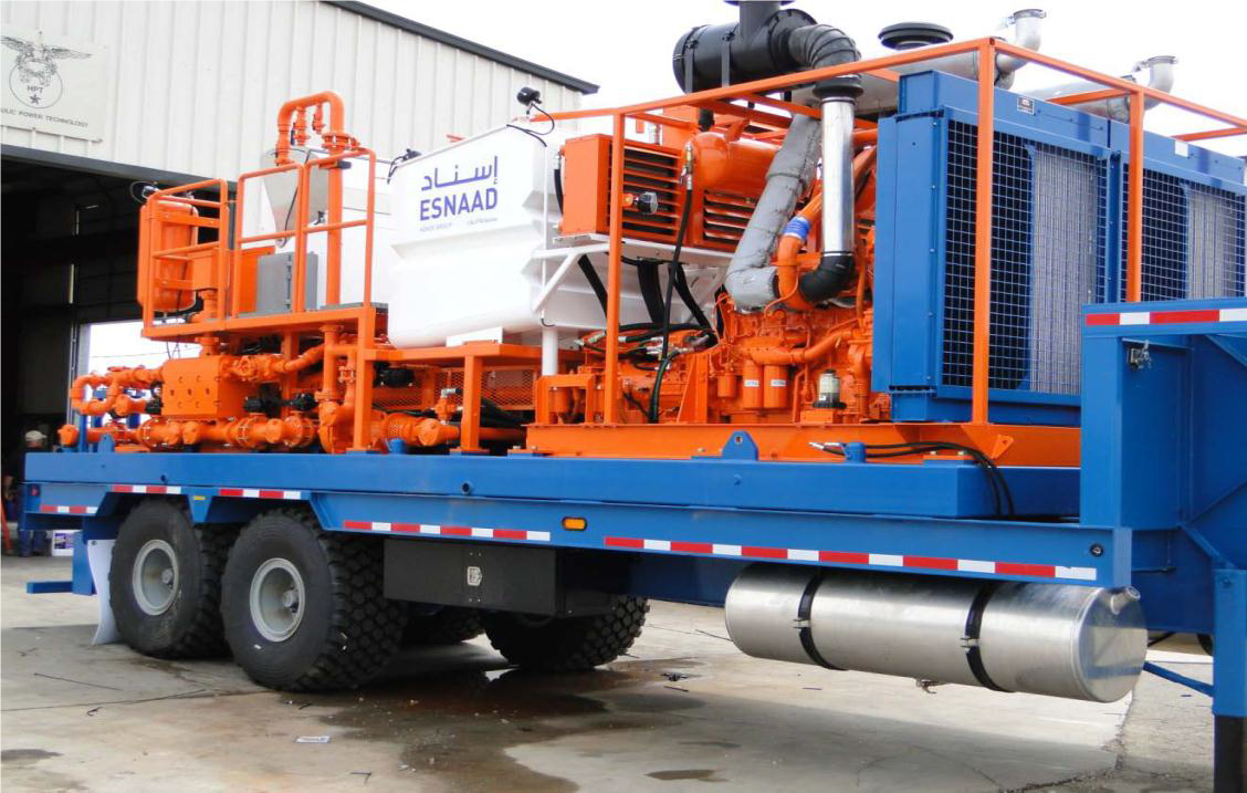 Figure 5
The twin-pump unit integrated with a trailer. The unit is moved with a tractor to and from location.
The unit’s main components are described in the Table in below:
| Engine | Detriot Diesel (SERIES 60 600 bhp @2100 rpm) |
| Hydraulic Pump Drive | Chelsea 859 PTO dirven from transmission PTO |
| Transmission | Allison 4700 OFS |
| Triplex Pumps | SPM TWS 600 (LH) with 3-1/2" Plungers |
| Stroke: 6 inches | |
| Bore: 3.5 inches | |
| Gear Ratio: 4.6:1 | |
| Max Discharge Pressure: 10,400psig | |
| Max Speed: 450 rpm (2070 rpm input) | |
| SPM TWS 600 (RH) with 4-1/2" Plungers | |
| Stroke: 6 inches | |
| Bore: 4.5 inches | |
| Gear Ratio: 4.6:1 | |
| Max Discharge Pressure: 6,290 psig | |
| Max Speed: 450 rpm (2070) rpm input) | |
| Driveline | Spicer 1810 series |
| Centrifugal Pumps | Mission: |
| 5" x 4" x 14" Boost Pump | |
| 4" x 3" x 13" Mix/Fill Pump | |
| Hydraulic Pumps and Motors | Vane Type: Denison |
| Gear Type: Metaris | |
| Hydraulic Heat Exchangers | Thermal Transfer (hydraulically driven) |
| Hydraulic Filtration | Donaldson |
| Hydraulic Accessories | Sun Hydraulics, Denison, DMIC and Wika |
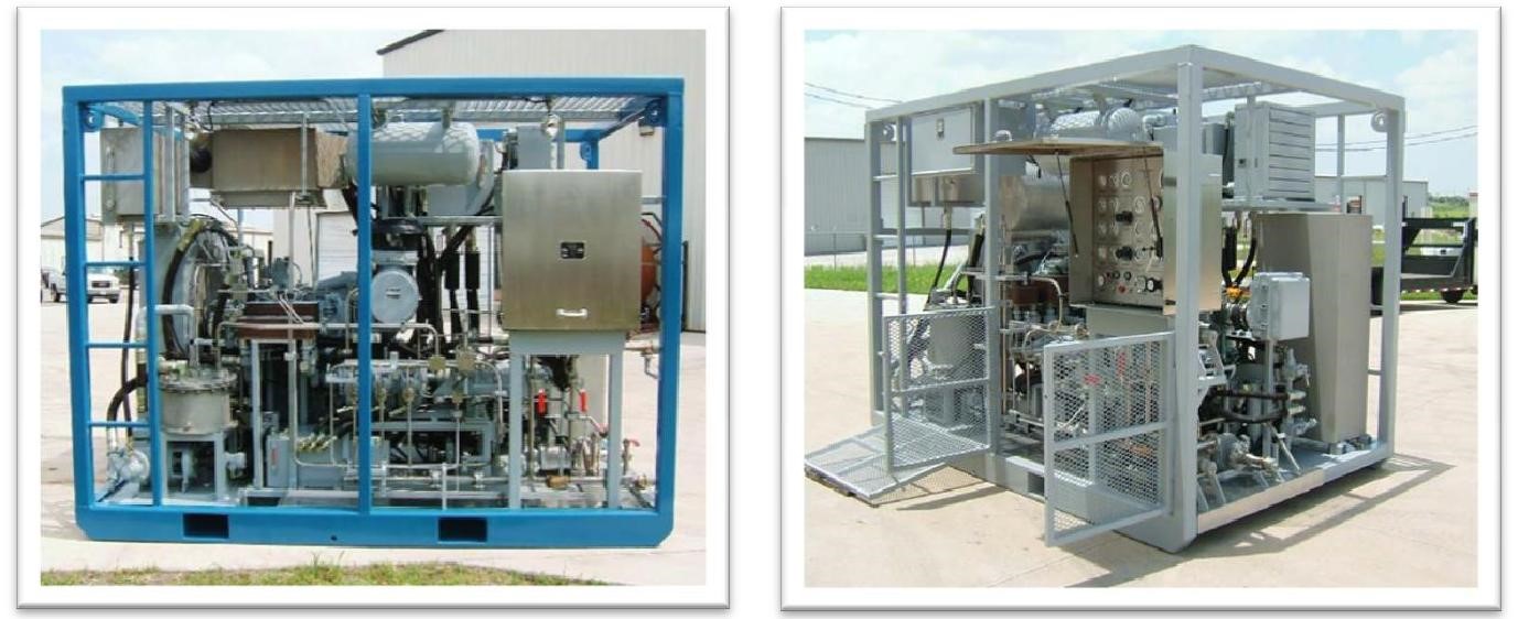
NITROGEN PUMP
SHAH PETROLEUM’s 180K Nitrogen Unit is capable to supply Gaseous nitrogen at flow rates up to 180,000 SCFH (3000 SCFM) and pressures up to 10,000 psig. The minimum outlet gas temperature at full rate will not be lower than 70 Degrees Fahrenheit. The energy required to vaporize the liquid nitrogen comes from two Sources: engine heat recovery and hydraulic system heat recovery. More specifically, approximately, 250 hp (636,108 Btu/hr) is captured from the engine exhaust, 300 hp (763,330 Btu/hr) is captured from the engine coolant, and 400 hp (1,017,773 Btu/hr) can be captured from the unit’s hydraulic system. The heat recovered from the hydraulics is transferred to the engine coolant circuit through a brazed-plate style heat exchanger. The total energy captured from the coolant and hydraulics is then used to vaporize liquid Nitrogen in the nitrogen pot vaporizer. The heat captured from the exhaust is used directly to vaporize liquid nitrogen in the exhaust-nitrogen heat exchanger.
The Nitrogen pump is used for:
- Nitrogen can be used in cementing to generate foamed cement.
- Nitrogen can be used in stimulation services as an artificial energizer.
- Nitrogen can also be used with coiled tubing lift fluids and in cleaning out the well
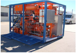
Figure 6
The Nitrogen Pumping Unit is mounted to a heavy duty oil-field type skid and surrounded by a protective frame. Both the skid and protective frame are constructed of mild steel with both square and rectangular hollow sections of grade ASTM 500-99-Gr. B. The nitrogen unit can be moved via the forklift tubes that are incorporated into the base skid or the four lift eyes on the protective frame.
CAPACITIES
| Maximum pressure (LN2 Discharge) | 10,000 psig |
| Maximum Flow Rate | 180,000 SCFH (3000 SCFM) |
| Minimum Flow Rate | 180 SCFM |
| Hydraulic reservoir | 96 Gallons |
| Diesel fuel reservoir | 140 Gallons |
| Pneumatic reservoir | 30 Gallons |
DESIGN FEATURES
| Engine | Caterpillar 3408TA-525 HP @ 2100 rpm |
| Mechanical Engine | |
| Pump Drivers | Durst 3PD08 pump drive and Durst 2PD06 pump drive. |
| Triplex pump | ACD GUPD (Externally Lubricated) |
| Triplex Druve Hydraulic Circuit | Closed loop, variable displacement pumps and gear motors. |
| Auxiliary Water Pump | Positive Displacement, Gear type |
| Cryogenic Boost Pump | ACD—1-1/2” x 2-1/2” x 6 “, centrifugal |
| Auxiliary Water Hydraulic Circuit | Open loop, gear pump supplying gear motor on the Auxialiary Water Pump |
| Cryogenic Boost Pump | Open loop, gear pump supplying piston motor on cryogenic boost pump |
| Heat recovery heat exchanger for engine exhaust | Finned tube style heat exchanger/vaporizer system (exhaust to nitrogen) |
| Heat recovery heat exchanger for hydraulic system | Brazed Plates design (oil to glycol). Two Heat exchangers. First for case drain oil and second for triplex drive gear motor/heat generation circuit oil. |
| Heat recovery heat exchanger for engine coolant | “Pot” type, rated for 180,000 SCFH |
| Triplex External Lubrication Circuit | Hydraulically driven warm end lubrication and lube oil cooling circuit provides excellent lubrication for low speed operations. Consist of a gear type motor pump combo and hydraulically driven fan hear exchanger |
| Heat Recovery System | The heat recovery system of this unit is a unique system that utilizes the engine coolant flow with the addition of an expansion tank regulating coolant pressure in the system |
BATCH MIXER
The batch mixer skid mixes and re-circulates Acid, cement, and chemicals for the pumping unit. It is equipped with two 50-bbl blending
Tanks capable of handling large volumes of Acid mixture.
Two centrifugal pumps are capable of transferring fluids from remote sources. In addition, they
re-circulate cement slurry back to the tanks, and discharge fluids to the pumping unit.
The Batch Mixer is used for:
- Blends a uniform and consistent Acid mixture in large amounts
- Transfers fluids from remote sources
- Allows for pneumatic feeding of dry chemical
- Re-circulates Acid mixture back to the blending tanks
- Delivers Acid mixture or fluids to the pumping unit
Equipment
- Diesel engine with air start
- Mixing/pressurize pump
- Two 50-bbl batch tanks
- Barrel-tank level gauges.

SPECIFICATIONS
| Skid type | Offshore and land skid |
| Length | 301 in (7,645 mm) |
| Width | 102 in (2,591 mm) |
| Height | 122 in (3,099 mm) |
| Weight | 24,948 Ibs. (11,320 kg) |
| Agitator (2) | Hydraulically-driven |
| Centrifugal pump (2) | RA45 |
| Engine | Cummins C6-8.3 230Bhp @2400 RPM |
| Hydraulic power pack | Denison T6CCM pump with MV4SC and |
| M4C motors | |
| Gauges{tank level) | Bbl |
| Residence tank | 2 x 50 bbl |
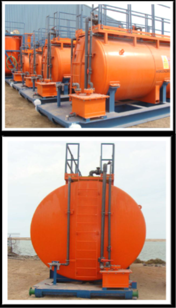
ACID TANK
The primary function of the Acid Tanks is to store and transport raw HCL Acid. The Acid Tanks is a skid mounted horizontal cylinder shape has internal rubber lining to protect tanks body from corrosion. Built in with a small tank act as neutralization unit for the acid vapors.
OIL WELL PUMPING AND STIMULATION SERVICES
A full range of chemical and hydraulic stimulation techniques are offered, either within the high pressure pumping service line or as a combined operation with coiled tubing or Nitrogen Pumping Systems.
The diverse range of operations, from flow line and completion flushing to matrix acid, are serviced from the extensive fleet of pumping and fluid handling equipment on inventory. With a focused management and engineering support team, SHAH PETROLEUM & CHEMICAL SERVICES provide a complete stimulation service.
SHAH PETROLEUM & CHEMICAL SERVICES state of the art high pressure twin pumping units contribute high role of our operations success and performance caliber. Our stimulation equipment are complete with all necessary auxiliaries such as water and acid tanks and choke manifolds as well as high pressure treating iron and valves to provide a complete service package.
SHAH PETROLEUM & CHEMICAL SERVICES combination of skilled personnel and proven equipment allows the company to supply a high quality and comprehensive stimulation service line.
Equipment is available for all environments from land operations, using truck –mounted units to offshore Zone 1 and Zone 2 systems. Our inventory includes mixing equipment suitable for all oil well stimulation applications.
COILED TUBING SERVICES
SHAH PETROLEUM & CHEMICAL SERVICES offer a comprehensive coiled tubing service based on a wide range of proven abilities. With units suitable for operation in Zone 1 and Zone 2, SHAH PETROLEUM & CHEMICAL SERVICES coiled tubing product line is well supported by numerous auxiliary facilities and functions. Equipment is drawn from the pumping and nitrogen service lines as required, whilst dedicated support of our coiled tubing extend the scope of operation for wide variety of Onshore and Off-shore applications.
SHAH PETROLEUM & CHEMICAL SERVICES ‘s Zone 2 rated coiled tubing units are diesel powered, four piece units, Separate control cabin and hydraulic power packs with adjustable hydraulic lifting jacks provide the localized control and hydraulic pumps required to drive different injector models. Reel angular positioning system allows accurate pipe guidance through injector and well head. The Zone 2 rated units is capable of running the complete range of coiled tubing pipe sizes available today.
The Zone 2 coiled tubing suite of equipment is supported by auxiliary equipment such extending the range of applications to cover interventions that are rig assisted, stand alone both onshore and Off-shore.

NITROGEN TREATMENT SERVICES
Nitrogen pumping is offered both as a service line in its own right and as a support service to other SHAH PETROLEUM & CHEMICAL SERVICES product lines with applications varying from gas lifting wellbore cleanouts and process plant purging to nitrified acid and foam diversion.
SHAH PETROLEUM & CHEMICAL SERVICES along with our successful alliance with Highly reputed Service Companies provide a high quality range of nitrogen converters from ambient vaporizers for low volume and pressure applications, to diesel powered Zone 2 rated units capable of 10,000 psi and 180,000 SCF / HR. Liquid nitrogen transport tanks and high pressure treating iron are supplied from inventory to provide a complete service package.
OIL WELL CEMENTING SERVICES

MAINTENANCE
MAINTENANCE PRACTICES
The SHAH PETROLEUM & CHEMICAL SERVICES fleet of equipment currently consists of the following major items:
- 1 Twin Pumping Unit
- 1 Coiled Tubing Unit
- 1 Batch Mixer
- 1 Nitrogen Pumping Package
- 1 Safety Caravan
- 4 Fluid Storage Tanks 500 BBl.
- 2 Acid Tanks 2000 Gal.
- 2 Acid Tanks 4000 Gal.
- 1 Acid Tanks 10000 Gal.
Additional the company has planning in 2012 for the purchase of new one complete Stimulation Package. Including same equipment as mentioned in above.
Properly maintained equipment is critical to successful conduct of Company operation and together with people and products forms the basis of SHAH PETROLEUM & CHEMICAL SERVICES value proposition. As such equipment maintenance and inspection forms a major part of SHAH PETROLEUM & CHEMICAL SERVICES QHSE program, specifically preventive maintenance.
The Maintenance Department within SHAH PETROLEUM & CHEMICAL SERVICES currently employs a qualified personnel trained and or experienced in mechanical, hydraulics, pneumatics, electrical and control system. Additional support to this group is provided by operational field personnel. Additional technical support is provided by world class suppliers who offer 24 hours service support and frequent supplier visits to the facility for routine equipment inspection, training and or commissioning services.
The majority of SHAH PETROLEUM & CHEMICAL SERVICES equipment such as Twin Pumping Unit, Coiled Tubing Unit and Nitrogen Pumping Unit has been purchased from leading USA based suppliers, as such the preventive maintenance program supplied with the equipment are informative and detailed. These documents are assimilated by the Company’s maintenance department and utilized in the Company Preventive Maintenance Program, specifically:
- Operation Checklist
- Preventive Maintenance Report
- Annual Inspection
Operation Checklist
Performed by equipment operator; designed to ensure the unit is job ready and is in safe operating condition. This may include regulatory pre and post-trip inspections.
PM Report:
Performed by the Maintenance Department at defined maximum frequencies to identify problems before they result in failures during operation of the unit. The following defined frequencies (whichever occurs first) are to be used.
– 300 engine hours
– 180 calendar days
– 6000 vehicle miles/10,000 vehicle kilometers
Use of any frequency exceeding this maximum will require an exemption approved by Department management.
Annual Inspection:
The trigger for annual inspection is one calendar year. Annual Inspection includes all the checks done on PM List as well as regulatory requirements such as tank testing and all inspections required by various governmental agencies. Separate Report must be completed for Annual Inspection and PM when documenting the Annual inspection.
Maintenance Report Procedures
The procedure for Equipment Maintenance details the process by which maintenance report is conducted and documented on ESNNAD equipment. The various form and inspection reports form an important part of that system and process.
Additional checklists and inspection reports are available for the wide variety of equipment utilized by ESNNAD and are available upon request.
Included in the following pages of this section are:
- Maintenance Report Procedure Flowchart.
- Well Services Maintenance Work Instruction - WI-OSD-WSD-002
- Operation Checklists, PM Reports and Inspection forms